
Benefits at a glance
- Robust and economical
- Dry-running
- Modular design
- Reliable and resilient
- Available as individual units
- Comprehensive range of accessories
- Frequency control possible
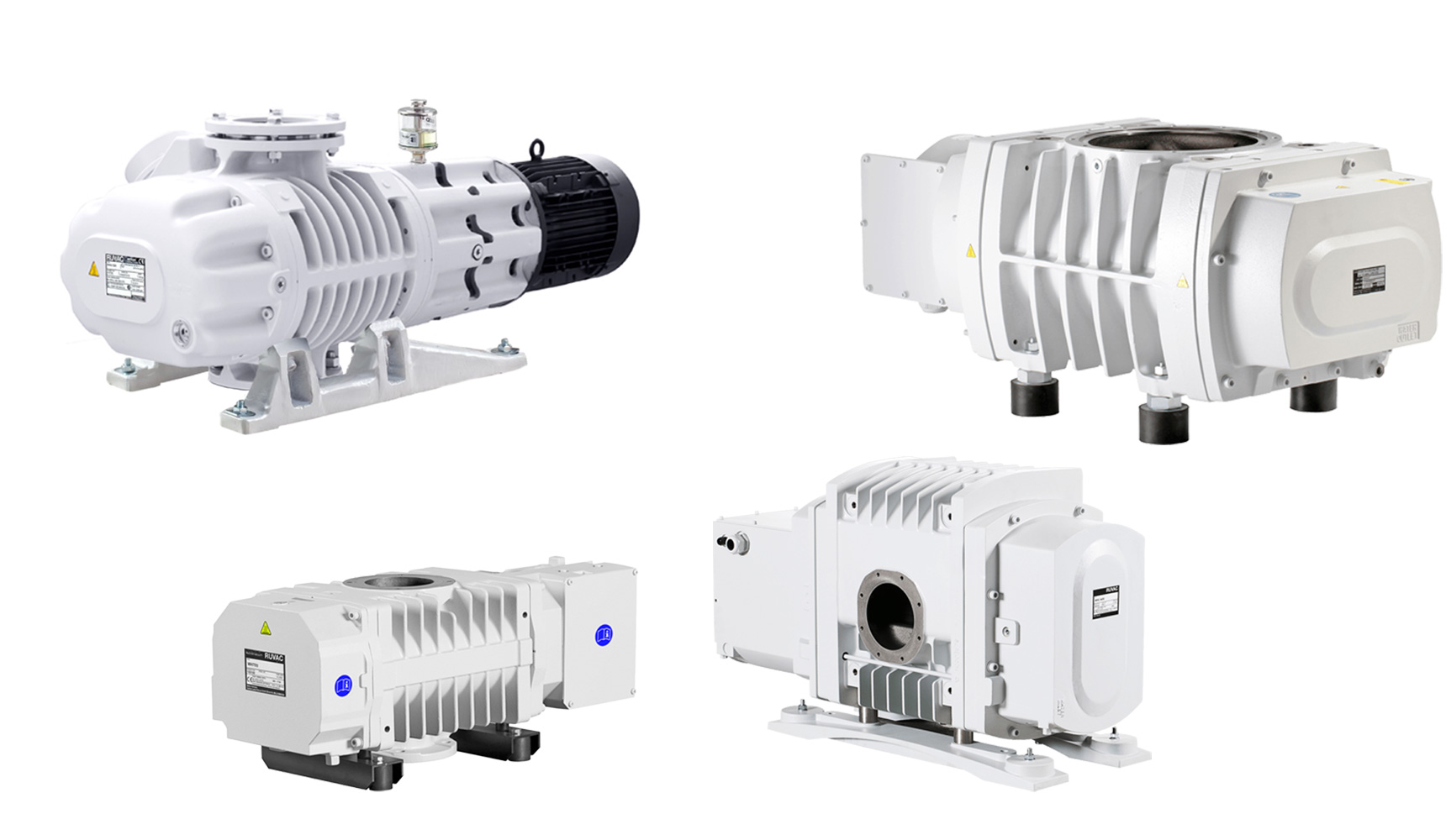
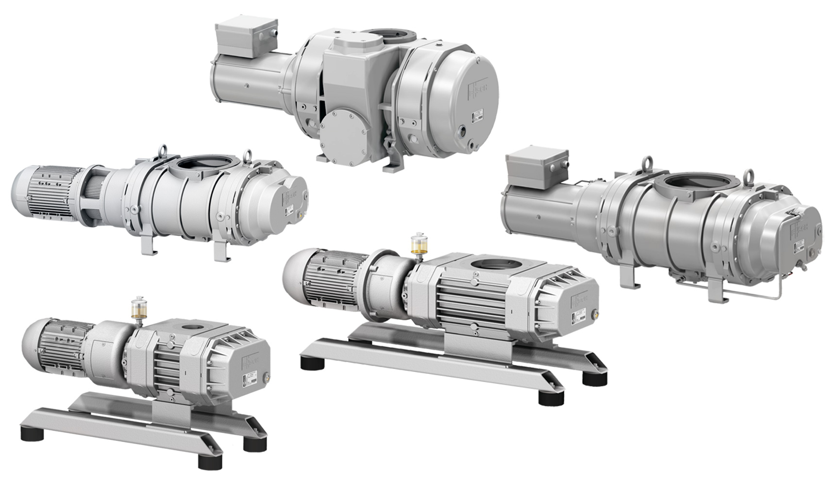
Roots vacuum pumps, also known as vacuum boosters, belong to the dry-running vacuum pumps which, together with backing pumps, cover a wide range of applications in which high pumping speeds are required. Vacuum boosters operate completely contact-free and without sealing liquids such as oil or water in the working chamber, although in most models the two gears of the synchronising gear and the bearings for the impeller shaft are lubricated with oil. Some of the pumps are equipped with a bypass valve.
Application examples
General industry
- Extraction systems
- Drying
- Aeration
- various process engineering applications
- Vacuum conveying
Environmental technology
- Extraction systems
- Aeration systems
- Drying systems
- Gas circulation
- Domestic sewage treatment plants
Benefits at a glance
- robust and economical
- dry-running
- modular design
- reliable and resilient
- available as individual units
- comprehensive range of accessories
- frequency control possible
Application examples
General industry
- Extraction systems
- Drying
- Aeration
- various process engineering applications
- Vacuum conveying
Environmental technology
- Extraction systems
- Aeration systems
- Drying systems
- Gas circulation
- Domestic sewage treatment plants
Operating principle
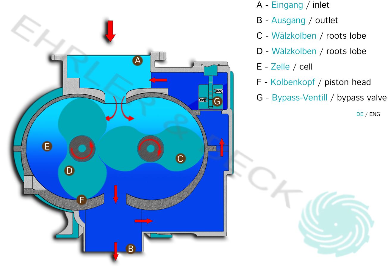
The individual Roots vacuum pumps were designed for use in pump units, in combination with a rotary vane pump as the backing pump. Roots vacuum pumps, also called vacuum boosters, run dry and without contact: two synchronised Roots pistons turning in opposite directions convey the gas without touching each other or the housing. Through the inlet (A), air flows into the housing, into the pumping cell formed by the two Roots pistons (C, D). The cell is then separated from the inlet by the following piston head (F). The air in the cell (E) is now conveyed onwards without reduction in volume until it reaches the outlet (B), from where air at higher absolute pressure is pushed from the pressure side into the arriving cell and is then discharged. Some models are equipped with an automatic bypass valve (G), which limits the pressure difference between inlet and outlet.
*This description does not take into account each manufacturer’s approach to the technology, but is a general description that attempts to cover the basic operating principle.